Step-by-step tips for your customers’ motor issues
For some service technicians, motor repair really means motor replacement. After all, if you don’t know how to fix a broken motor, changing a malfunctioning unit may be your only option.
For others, repairing the small electric motors that power pool and spa pumps is a useful way to keep down the cost for the customer while earning a tidy profit.
When it comes to motor service, Elias Duran is an acknowledged expert. When he finishes his weekly service route, his attention often turns to motor repair — and he’s been teaching the basics of motor teardown and repair for more than a decade.
The owner of Duran’s Pool & Spa Service in North Hills, Calif., offers some pointers for technicians to keep in mind as they approach ailing motors:
Always use quality replacement parts, as recommended by the motor manufacturer. When tearing down a motor or replacing parts, never force anything — or you may end up replacing additional parts.
If you need help with a motor, take it to a reputable motor-repair shop.
Be safety-conscious when working with electricity. Always be sure the motor is grounded before connecting the power. Another must: The power source needs to be disconnected before you begin working on the motor. Also be sure you are using the correct electric voltage.
Remember that some slight differences may occur between different motor models. When in doubt, consult the manufacturer’s handbook for the specific model you’re repairing. In the accompanying pictorial, Duran offers instructions on how to tear down and reassemble a motor. He also provides detailed troubleshooting tips and instruction on how to replace ball bearings, perhaps the most common form of motor repair.
Tools for the job
Flat-head screwdriver Small mallet Socket wrench or nut driver (1/4- to 5/16-inch, as needed) Bearing puller Bearing drivers (two sizes) Ohmmeter Plumber’s sand cloth or emery paper Red insulating varnish spray (for windings) Spray paint (for motor housing) Masking tape Marking pen
1
of 20
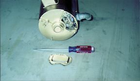
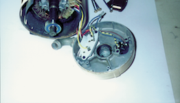
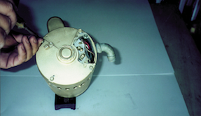
1. Remove the terminal connection coverLoosen the terminal conne…
1. Remove the terminal connection coverLoosen the terminal connection cover’s two screws with a flat-head screwdriver and remove the terminal connection cover. Check connections on terminal board. Test the electrical-line leads with an ammeter/voltmeter while supplying electric power; disconnect power before proceeding.
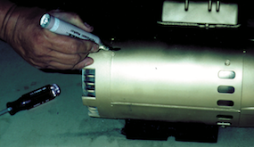
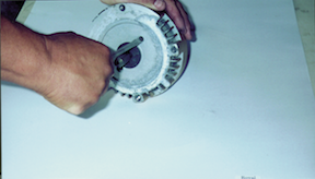
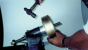
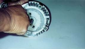
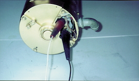
2. Mark the end-bell/stator alignmentUsing a marking pen or mask…
2. Mark the end-bell/stator alignmentUsing a marking pen or masking tape, mark the position of both end bells for proper alignment with the stator.
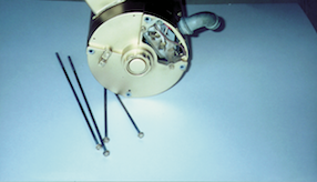
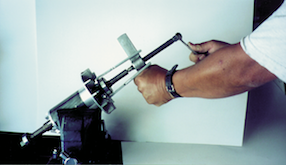
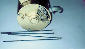
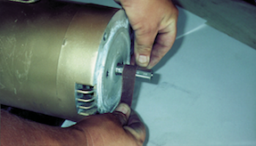
3. Remove through boltsRemove the four through bolts using the a…
3. Remove through boltsRemove the four through bolts using the appropriately sized socket wrench or nut driver; bolt heads will vary from 1/4- to 5/16-inches.
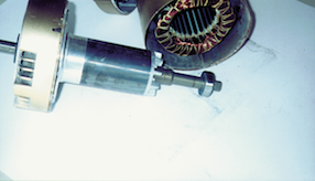
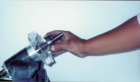
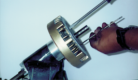
10. Remove the ball bearingsUsing a bearing puller, remove the l…
10. Remove the ball bearingsUsing a bearing puller, remove the lock collar, ball bearing and backing plate from the shaft end — and the smaller ball bearing from the opposite-shaft end.
11. Replace the front bearings: Reinstall the backing plate on t…
11. Replace the front bearings: Reinstall the backing plate on the shaft end. Install the new bearing. The bearing should only be put on with a bearing press or using a pipe or collar piece the same diameter of the inner race (the steel ring of the bearing that makes contact with the motor shaft), tapped lightly by a mallet until seated against the appropriate shaft shoulder or stop. Force should be applied only to this inner race to avoid damaging the bearing.
12. Replace the rear bearings: Refer to the procedure described …
12. Replace the rear bearings: Refer to the procedure described in Step 11, excluding the backing plate.
13. Replace the shaft-end bell: Slide the shaft-end bell onto th…
13. Replace the shaft-end bell: Slide the shaft-end bell onto the shaft; tap the end bell with a mallet if necessary. Hint: Thread two appropriately sized through bolts into the locking plate to use as guides when replacing the locking ring screws. (Bolts can be salvaged from an old motor.)
14. Replace the locking ring screws: Replace the two locking rin…
14. Replace the locking ring screws: Replace the two locking ring screws in the shaft-end bell. If you use the hint from Step 13, leave one “guide” through bolt in place while you replace the other; then replace the second screw. Tighten the two screws.
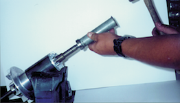
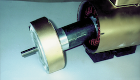
15. Reinstall the end bell: Slide the shaft-end bell back into t…
15. Reinstall the end bell: Slide the shaft-end bell back into the motor for reassembly. Be sure to match the alignment marks on the end bell and stator. Tap the end bell lightly with a mallet if necessary.
16. Replace the REAR-end bell: Slip the rear-end bell back into …
16. Replace the REAR-end bell: Slip the rear-end bell back into place after replacing the bearing spring. Be careful not to pinch any wires between parts, and match the alignment marks on the end bell and the stator. Tap the end bell lightly with the mallet if needed.
17. Replace the through bolts: Replace the four through bolts an…
17. Replace the through bolts: Replace the four through bolts and tighten them as you would tighten the lug nuts on a car wheel — that is, a little at a time while rotating from one to another until they are all tight.
20. Replace the terminal connection cover: Replace the terminal …
20. Replace the terminal connection cover: Replace the terminal connection cover and tighten the two bolts.
An invaluable skill for any service technician, motor tear down and reassembly are needed for most repairs. Follow the steps in this slideshow for tear-down, bearing replacement and reassembly.
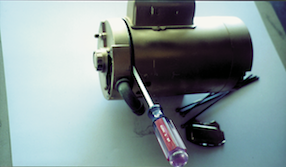
The last step
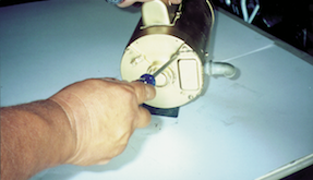
You’ve finished the motor reassembly, but before reinstalling the unit, Elias Duran, owner of Duran’s Pool & Spa Service in North Hills, Calif., suggests taking one more step: If the motor’s cover is scratched, rusted or faded, give it a new coat of paint.
First clean the motor cover, then mask the nameplate and other important labels on the face of the motor with tape. (It’s crucial to protect the nameplate before painting because it bears information critical for future troubleshooting or motor replacement.)
Now apply a light coat of spray paint to give the motor a clean, rejuvenated appearance.
A final hint from Duran: Use the original paint color — or, if your customer prefers, use a color that matches the other equipment on the pad.
We use cookies on our website to give you the most relevant experience by remembering your preferences and repeat visits. By clicking “Accept”, you consent to the use of ALL the cookies. However you may visit Cookie Settings to provide a controlled consent.
This website uses cookies to improve your experience while you navigate through the website. Out of these cookies, the cookies that are categorized as necessary are stored on your browser as they are essential for the working of basic functionalities of the website. We also use third-party cookies that help us analyze and understand how you use this website. These cookies will be stored in your browser only with your consent. You also have the option to opt-out of these cookies. But opting out of some of these cookies may have an effect on your browsing experience.
Necessary cookies are absolutely essential for the website to function properly. These cookies ensure basic functionalities and security features of the website, anonymously.
Cookie
Duration
Description
cookielawinfo-checkbox-analytics
11 months
This cookie is set by GDPR Cookie Consent plugin. The cookie is used to store the user consent for the cookies in the category "Analytics".
cookielawinfo-checkbox-functional
11 months
The cookie is set by GDPR cookie consent to record the user consent for the cookies in the category "Functional".
cookielawinfo-checkbox-necessary
11 months
This cookie is set by GDPR Cookie Consent plugin. The cookies is used to store the user consent for the cookies in the category "Necessary".
cookielawinfo-checkbox-others
11 months
This cookie is set by GDPR Cookie Consent plugin. The cookie is used to store the user consent for the cookies in the category "Other.
cookielawinfo-checkbox-performance
11 months
This cookie is set by GDPR Cookie Consent plugin. The cookie is used to store the user consent for the cookies in the category "Performance".
viewed_cookie_policy
11 months
The cookie is set by the GDPR Cookie Consent plugin and is used to store whether or not user has consented to the use of cookies. It does not store any personal data.
wordpress_test_cookie
session
This cookie is used to check if the cookies are enabled on the users' browser.
Functional cookies help to perform certain functionalities like sharing the content of the website on social media platforms, collect feedbacks, and other third-party features.
Performance cookies are used to understand and analyze the key performance indexes of the website which helps in delivering a better user experience for the visitors.
Analytical cookies are used to understand how visitors interact with the website. These cookies help provide information on metrics the number of visitors, bounce rate, traffic source, etc.
Cookie
Duration
Description
_ga
2 years
The _ga cookie, installed by Google Analytics, calculates visitor, session and campaign data and also keeps track of site usage for the site's analytics report. The cookie stores information anonymously and assigns a randomly generated number to recognize unique visitors.
_gat
1 minute
This cookie is installed by Google Universal Analytics to restrain request rate and thus limit the collection of data on high traffic sites.
_gat_UA-
1 minute
A variation of the _gat cookie set by Google Analytics and Google Tag Manager to allow website owners to track visitor behaviour and measure site performance. The pattern element in the name contains the unique identity number of the account or website it relates to.
_gid
1 day
Installed by Google Analytics, _gid cookie stores information on how visitors use a website, while also creating an analytics report of the website's performance. Some of the data that are collected include the number of visitors, their source, and the pages they visit anonymously.
CONSENT
2 years
YouTube sets this cookie via embedded youtube-videos and registers anonymous statistical data.
Advertisement cookies are used to provide visitors with relevant ads and marketing campaigns. These cookies track visitors across websites and collect information to provide customized ads.
Cookie
Duration
Description
loc
never
AddThis sets this geolocation cookie to help understand the location of users who share the information.
OAGEO
session
OpenX sets this cookie to avoid the repeated display of the same ad.
OAID
1 year
Cookie set to record whether the user has opted out of the collection of information by the AdsWizz Service Cookies.
VISITOR_INFO1_LIVE
5 months 27 days
A cookie set by YouTube to measure bandwidth that determines whether the user gets the new or old player interface.
YSC
session
YSC cookie is set by Youtube and is used to track the views of embedded videos on Youtube pages.
yt-remote-connected-devices
never
YouTube sets this cookie to store the video preferences of the user using embedded YouTube video.
yt-remote-device-id
never
YouTube sets this cookie to store the video preferences of the user using embedded YouTube video.