On a project like this,sometimes the beginning can be the toughest, because there’s so much detail. That especially holds true here, where we’re starting with the most technically difficult part.
Each feature is massive — and almost all of them interconnect with at least one other element in the yard. A lazy river feeds the surf simulator. The main pool shares a wall with the basement — and that wall features a shark tank through which swimmers can look into the basement and vice versa.
These interactions between elements have created the most significant challenges in this design so far.
A complete overview of the project can be found in the Nov. 19 issue. Here I’m providing an update of the yard, which we expect to keep us busy for at least another year.
At this point, we have made serious headway constructing the shark tank, a balancing act in itself. And we’ve broken ground on the master bedroom swim spa. While this is happening on the site, we’re using a sophisticated technology to fine-tune the river’s flow so the adjacent surf simulator doesn’t manhandle swimmers.
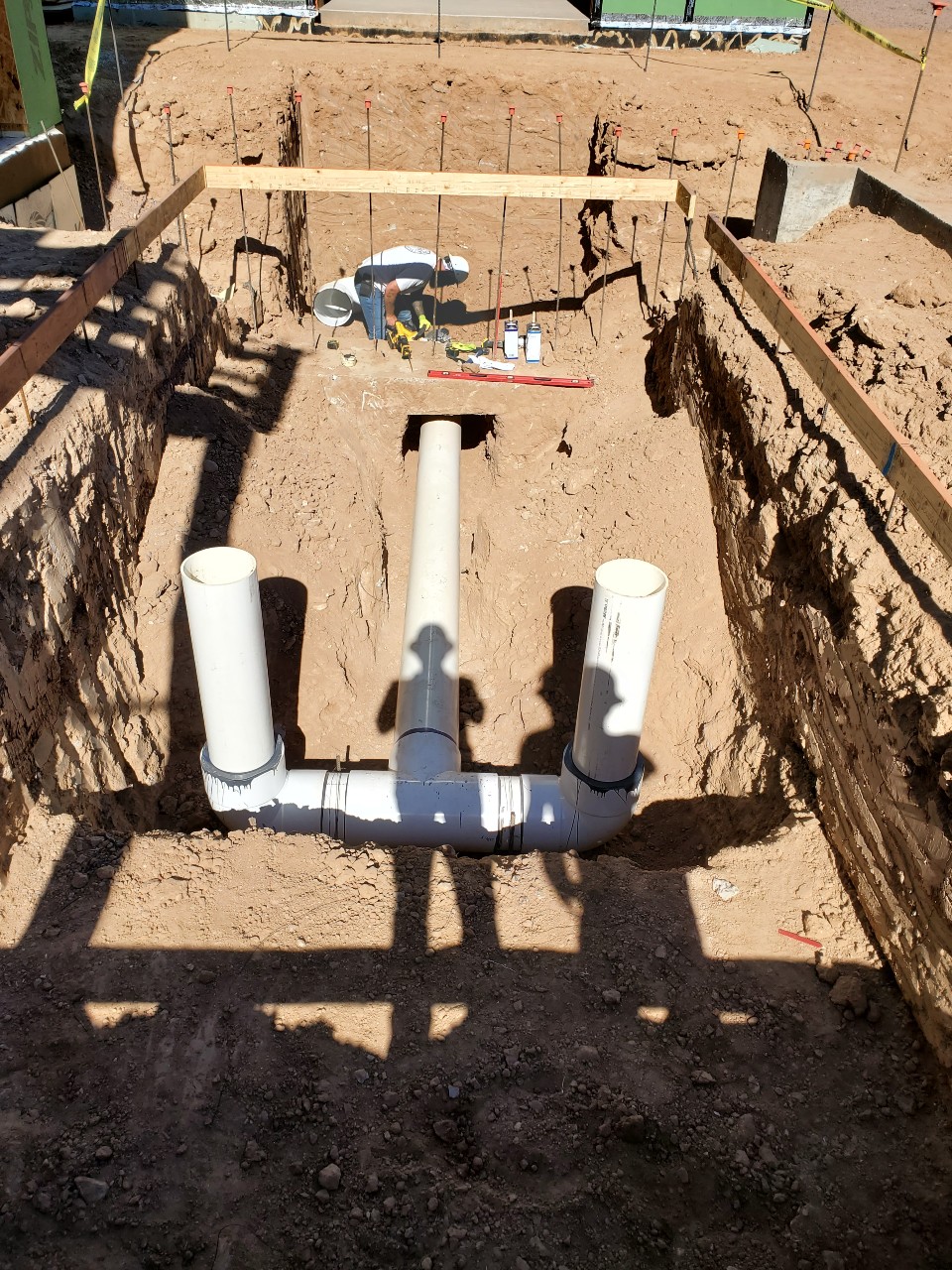
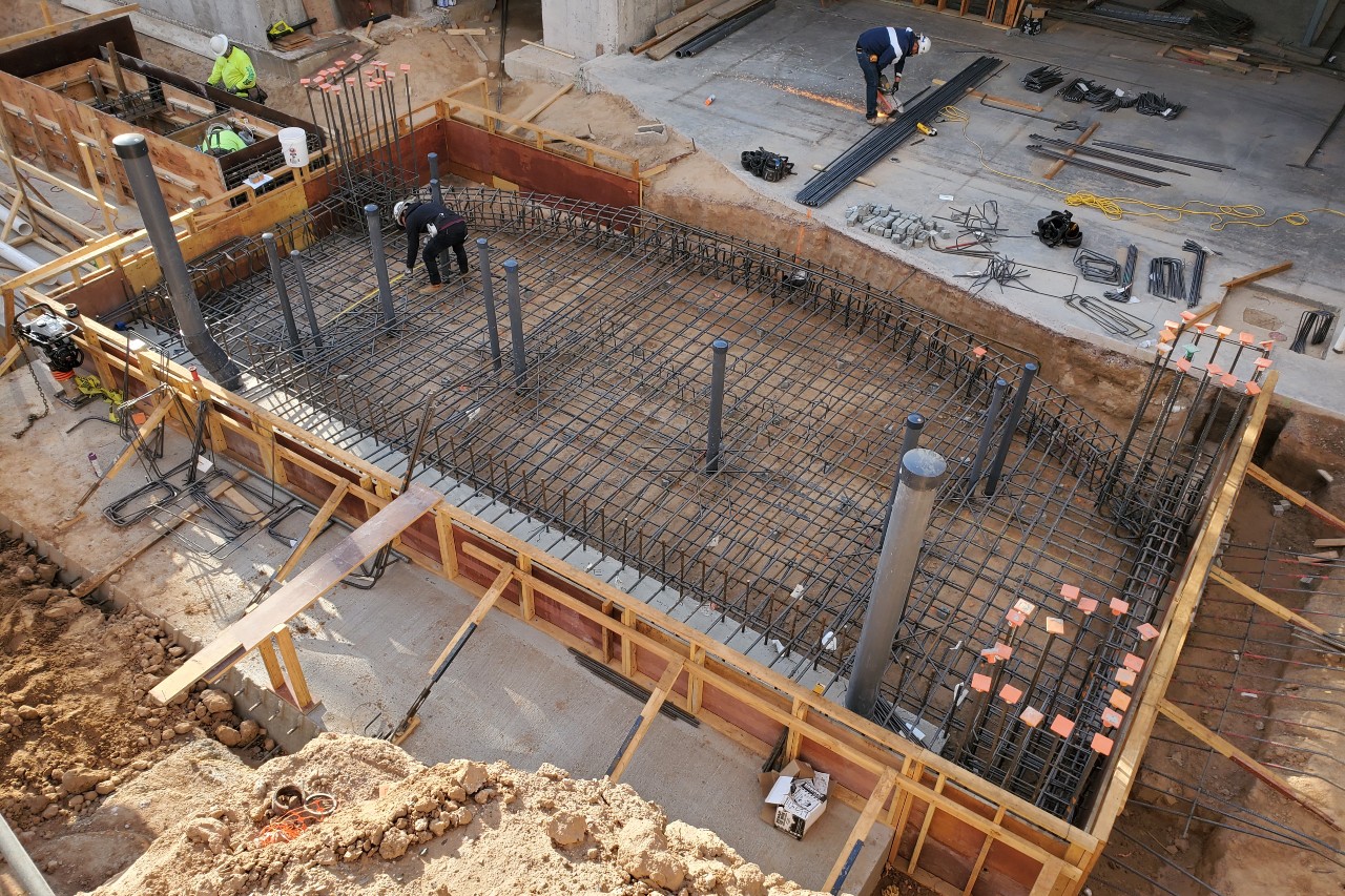
Crews broke ground on the master bedroom swim spa. Here, they can be seen placing the 12-inch plumbing for the current system.
Working underground
Before we could get to the basement-level shark tank, we started 30 feet below grade, with a remote surge tank. With that poured, formed and backfilled, we are now able to work at basement grade, 19 feet below finish floor level.
Crews work on the remote surge tank, which broadens significantly below the portion in view here. It reaches 30 feet below grade. Above it will sit the main pool.
Acrylic panels will complicate any feature. Intensifying the difficulty here, three of the four windows are radiused — even the largest one, which measures 30-by-10 feet and will sit in the basement for optimal viewing. We needed curved windows to make the sharks comfortable. They continuously swim, even when they’re asleep, so they need rounded corners so they can easily swim in a circle without getting caught. So the tank is semi-round.
It will be cast-in-place, which must take place in three pours — first for the floor, second for the window frames. Next we place the largest window, before pouring the ceiling of the tank. Normally, we would cast the entire concrete framework, ceiling included, before placing the panels. But because of the largest window’s size, we have to install it before pouring the lid. We’ll protect the panel, then build all the shoring and form work for the tank’s ceiling. The other panels are small enough to maneuver after pouring is complete.
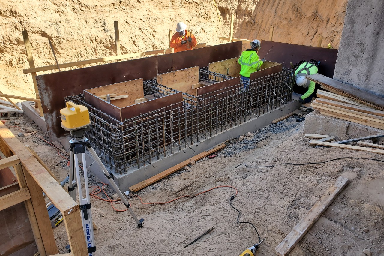
We needed to take this approach because of all the detail in the concrete. The floor and four columns all have their own set of complex rebates — the recesses or slots that the window is set into. The outside of the tank is square, while the inside is round, which further complicates the forming. Also, we couldn’t form and pour monolithically because we have horizontals in the floor and cap, then the verticals in the window framing.
The steel reinforcement takes this tank to another level. We are working with massive steel – #6, #7 and #8 bars. In addition to being more than double the thickness of typical pool steel, the bars are grade 60, which is considerably more rigid than the grade 40 bars we usually see.
There’s no way we could bend these on-site. Each bar needed to be prefabricated for its specific position. The steel came with a shop drawing dictating the exact location of every piece. The structural engineer provides drawings indicating the size and placement of each piece. Then the fabricator creates drawings for each bar, which go back to the engineer for cross-checking.
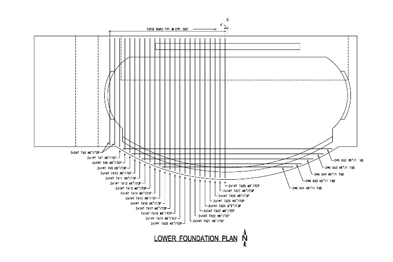
One in a set of drawings that dictate where each of the prefabricated bars must be placed.
Hundreds of bars, most weighing hundreds of pounds each, are assembled one by one, with no offsetting allowed. About 45 tons of steel is being used.
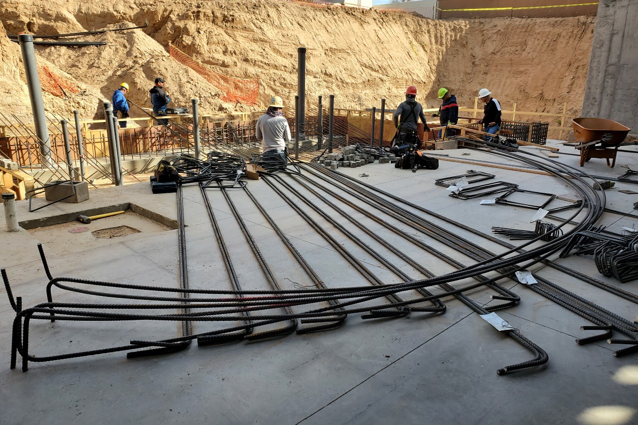
Because the structural steel was so large and of a higher grade, each bar had to be prefabricated off-site.
Intricate calculations
While that work takes place on-site, we’re fine-tuning other features on the design side.
One of the most interesting has been the lazy river. Several factors influence the success of a lazy river, including the pump power, river configuration and plumbing. You have the potential for all kinds of problem areas, such as eddies — those spirals of water where you can get stuck. You don’t want areas where the user just stops or has to swim their way back in. You also have to account for safety — the water can move too fast, send the user where you don’t want them to go, or even knock them down upon entry or egress. We’re planning to create rapids in this river, so we need to be very careful, both to attain adequate water flow and account for safety.
Some factors on this project can wreak havoc if they’re not properly managed. The 540-foot length, for instance, can have an impact. But here’s the most important: the adjacent Flowrider surf simulator, which pulls water from the river. Our 10 horsepower River Flow pumps will move 1,200 to 1,500 gallons per minute, but the surf machine will generate about 17,000 gpm — more than 10 times what the Riverflow pump produces. So we have to make sure that the surf machine doesn’t cavitate the river or create unsafe conditions.
Some aspects of the water movement are fairly intuitive to predict: We know, for instance, that it will flow more easily along round corners than harsh angles. But other times, the water’s performance seems completely illogical.
So for a project of this magnitude, we decided to implement a process called Computational Fluid Dynamics analysis. A third party, Rand Worldwide, performed this using a program called ANSYS Fluent. The analysis takes all the relevant design factors into account to determine the varying speeds throughout the river, and at varying depths.
You don’t just perform one analysis. You do one, modify the design, then analyze again to see the effects. The drawing to the left shows our first analysis, taken on the very surface of the water, which has the most influence on the rider. The color indicates the speed, measured in feet per second.
You can see how the water surprises you sometimes. Like one section will have a red spot on an inside corner, so you wonder, “Why did it get faster there?” Then another corner does the opposite — the inside got slower. The water is very dynamic — it seems to pick and choose how it’s going to respond to its conditions. Thankfully, the software performs millions of calculations for the analysis.
In the analysis pictured, the large red area shows the water coming off the slide of the surf machine. (The surf machine is in the empty spot toward the bottom.) On the bottom right-hand side, where we see some red and some blue, the water just dead ends.
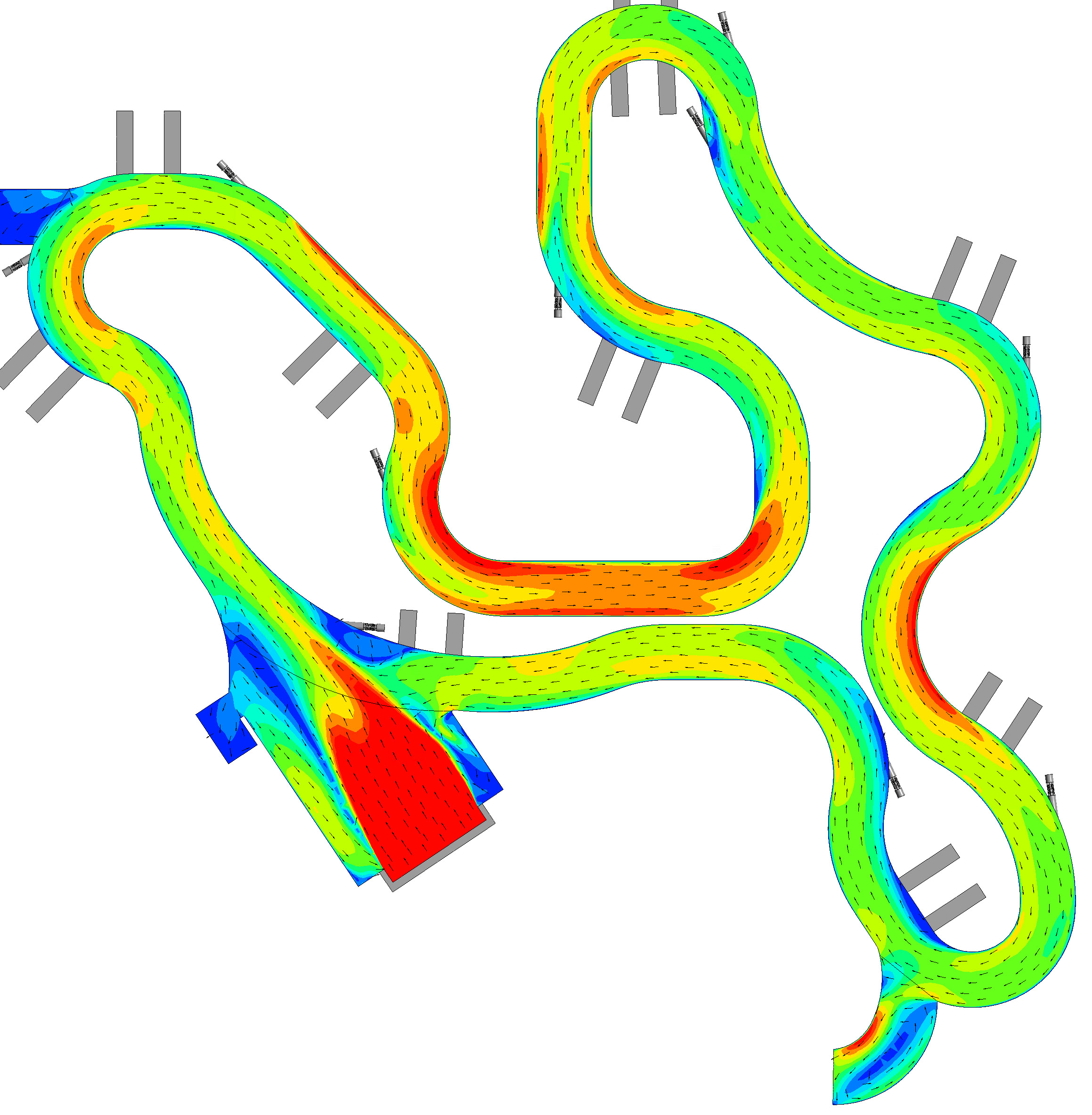
A Computational Fluid Dynamics analysis shows expected water speeds throughout the lazy river. Red is the fastest, at 4.5 to 5 feet per second. Yellow and orange are next fastest. In the dark blue areas the water barely moves, at 0 to 1 fps.
Based on the CFD, we made changes. One set of stairs had about 2 fps moving across it — enough to push a small child off their feet. So we redesigned that spot.
We also found a bank of three 10 hp pumps that didn’t affect the flow at all. We placed them there to help move users around a corner. When we saw that three didn’t work, we tried using just two, then one, but it didn’t help. Instead, we had to fix the geometry. I would have spent $30,000 on those extra pumps. Now, I can use them someplace else where they will provide more benefit. So you can see where the CFD analysis paid off, even at a $20,000 price tag.
Next we’re going to analyze the rapids. We’ll see whether adding speed bumps to the floor or tapering the bottom corners of the walls will increase the velocity enough to make it worth the while.