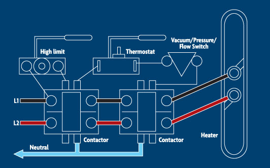
While water temperature is the most common spa customer complaint, it often has nothing to do with the integrity of the heater. Many hot tub components affect its heating ability and should be factored in when searching for a culprit. Understanding the system’s capabilities and limitations will determine your success.
In my experience, the most efficient ways to troubleshoot problems are to make a physical inspection, assess the incoming electrical service, check the mode of operation and evaluate the heater.
Make a physical inspection
If you see/hear/smell a problem, safety dictates the need to correct it before continuing. Whether the issue has anything to do with the heater or not, the corrective action often points you toward a solution.
A leaking pump seal might be overlooked unless you consider that water seldom leaks where air does not replace it in the plumbing. A bubble in the plumbing can cause the pressure switch to remain open or the water to not flow at all (air lock). Melted control input terminals can seem unrelated. However, for the temperature of a wire to rise to the melting point, electrical current must be moving in a circuit and a heater produces the most current in a spa. Depending on which terminal is melted, the heater circuit can be dead while other components might work just fine.
Assess the incoming electrical service
Wire size, type and disconnect considerations are critical to proper heater operation, but often input voltage is overlooked. Even when it is considered, it’s not always properly evaluated.
Checks must be performed to measure the exact voltage applied — that is, for a 240VAC reading from L1 to L2. Measuring 120 twice does not necessarily indicate the presence of 240VAC because either phase can feed back through another circuit. Measuring each phase to neutral and ground (120VAC at L1 and L2) is important to completely verify the service applied. Further troubleshooting should not be done until proper voltage to the control is restored.
Check the mode of operation
To effectively check the operation requires looking at functions selected to operate at specific times, such as filtration. But heating cannot take place without certain functions, and will be inhibited by others.
Case in point: Most people are aware that heating only takes place when water is circulating. “Circulation” is not the same from system to system, though. On 120VAC systems, selecting the high-speed or blower functions will eliminate the ability to heat due to service limitations.
In 240VAC systems with a 50amp breaker, heating can take place at the same time as high-speed and blower functions. If the blower is selected, however, the water often moves but does not circulate. On systems using two single-speed pumps, the jet function has a different plumbing circuit than the circulation function. Water moving through the jets does not indicate circulation for heating purposes.
In addition, just because you hear the pump running doesn’t mean the water is moving properly. Air locks, clogged or broken impellers, closed valves or jets, and dirty filters all can reduce circulation and affect heating. The inability to circulate correctly usually is indicated by the failure of one or more safety devices, such as the high-limit, pressure and flow switches.
Evaluate the heater
The heater is easy to verify and can be dropped from consideration in short order. Disconnect the heater wires and test between the terminals using an ohmmeter. A good element will read 9 to 12 ohms. A bad element will test open or infinite.
Remember, an element can have good resistance and still require replacement. Damage to the sheath can allow moisture into the element. Any connection (< infinite) between an element terminal and its sheath indicates that current will leak into the water. Heaters with a short to ground often cause the GFCI to trip. Infinite resistance between the element terminals and any resistance to ground are the only two instances that indicate a bad element.
Reconnect the wires and set the unit to heat. Use a voltmeter to monitor voltage at both heater terminals simultaneously. The right voltage indicates a good heater circuit.
A circuit with good voltage to the element and proper resistance must heat. Note: Insufficient heat can look similar to none at all, depending on the tests’ timing.
Losing voltage at the heater before reaching set point indicates a failed or out-of-tolerance switching device or safety (thermostat, pressure switch, high limit and the like). Failure to provide voltage to the element, heater relay or contactor may not indicate a bad device.
For example, poor flow through the manifold can cause the high limit to open. Though the high limit is the cause of the failure, the condition it monitors is actually at fault. Therefore, replacing it will not resolve the issue.
It’s always best to believe that safeties are doing their job and evaluate the conditions they monitor. Failing to do so can cause catastrophic problems later on.


