A well-done heater installation ensures years of trouble-free satisfaction for customers and techs. But installed incorrectly, a heater can become a service nightmare, subject to a variety of operational problems.
More importantly, these heaters pose a risk to customers and techs that must be dealt with — even if the techs had nothing to do with the installation. If you service a pool with an improperly installed heater and an injury occurs, you could be held liable whether you had anything to do with the accident or not. If you see installation-related problems, you must notify your client of the situation, preferably in writing. This will help you stay off the liability hook.
To do so, you must know what to look for when evaluating an installation. Although most requirements tend to be consistent among suppliers, you must always closely follow each manufacturer’s own installation guidelines at the job site.
Keeping your distance
The first step in a good installation concerns the heater’s placement relative to its surroundings — specifically, its clearances.
The American National Standards Institute helps out here by offering guidelines (ANSI Standard 2223.1), designed to keep heaters, whether installed indoors or out, at a safe distance from all combustible materials contained in nearby walls, landscaping or structures. (Because this standard sets clearance requirements based on the external temperatures of heaters, clearances may vary.)
• The rear and nonplumbed sides of the heater need at least 6 inches of clearance.
• The water-connection side should have a minimum of 12 inches of clearance — 18 inches is recommended.
• The front of the heater should have at least 24 inches of clearance.
Moreover, the following clearances are based on the National Fuel Gas Code and are universal for all gas-heater models:
• When installing a heater under an overhang, there must be at least 4 feet of vertical clearance from the top of the heater to the overhang, and the heater must be open on three sides.
• The top of the heater must be at least 5 feet below, or offset 4 feet from, the nearest opening to a building, such as a window or door; in addition, the top of the heater must be at least 3 feet above any forced-air inlets located within 10 feet of the unit.
All heaters must be installed at least 5 feet from the inside wall of a spa unless it is separated from the spa by a fence, wall or other permanent barrier.
A secure heating pad
The heater must be installed on a level, noncombustible base such as brick or concrete. If a new pad must be built, there should be a minimum of 1 foot of clearance on the pad for all sides of the heater.
If concrete cinder block is used as a base, it must be aligned so the cells all point the same way; the end should be left open. When hollow masonry is used, the pad must be at least 4 inches high — and covered with a 24-gauge (or heavier) piece of sheet metal. Another option: Check with your distributor for a synthetic, lightweight, noncombustible pad to set the heater on.
Next, consider the elements. If the heater is placed in an area exposed to high winds, the unit either must be installed at least 3 feet from the nearest wall, or a wind block must be constructed to help minimize the effect of wind reflecting into the heater. (Most manufacturers provide recommended wind levels at which a device known as a vent cap also is required. Some manufacturers now also equip their heaters with low-profile vent assemblies.)
Without proper air flow around the heater, efficient combustion is impossible and burnt fossil fuel cannot be safely vented. While this is an obvious concern outdoors, indoor installations are even more sensitive to such considerations — particularly with respect to venting.
Inside installations
The ground rules for heaters with sealed combustion chambers installed indoors are straightforward and rigid:
• If the heater is installed in a place where vented air comes from another interior room, the space where the heater is located must be connected to the additional airspace by two vents, and the combined area of the space where the heater is located and that additional room must represent at least 50 cubic feet per 1,000 BTUs of heater input. (The BTU input of any other gas-burning appliances in that space, such as a home water heater, also must be factored into this calculation.)
• The space must have two openings, one beginning 12 inches above the floor, the other 12 inches from the ceiling, per the code. The top opening is for replacement air (ventilation), while the bottom is for combustion air (what the heater uses).
• Each heater model has specific venting requirements to ensure proper combustion and prevent sooting. Manufacturers express venting requirements as square inches of net free air. A typical requirement is 1 square inch per 1,000 BTUs of input for an unobstructed opening. When venting heaters, don’t guess. Always consult the manufacturer or read the manual for venting sizing requirements for the specific model being used.
• For spaces vented to the outside, the space also must have top and bottom vents for the confined space. The openings must connect directly or be connected by ducts to the outdoors. Alternatively, the vents must connect to an area such as an attic or crawl space connected directly to the outdoors.
• Regardless of where the unit gets its air, indoor heater installations require a draft hood that sends combustion byproducts — particularly carbon monoxide — outside the building. Failure to meet this requirement can result in fire or carbon monoxide poisoning. (Some models have a built-in draft hood design that does not require an additional draft hood externally.)
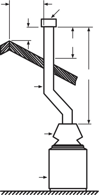
The diameter of the draft hood is based on the National Fuel Gas Code and may vary from model to model. Connected to the draft hood is the vent pipe, which vents products of combustion to the outside air; it must have a diameter equal to, or greater than, the draft hood.
While blower heaters don’t require as much room, the discharge opening in the vent pipe for other heater models must be at least 2 feet above the roof surface and at least 2 feet above the highest point on the roof within a l0-foot radius of the pipe location. Because the vent pipe is exposed to the elements, it also must be topped with an approved vent cap, which keeps wind and air from forcing products of combustion back down into the ventilation system.
In reaching this safe venting point, installers are urged by manufacturers to avoid horizontal piping runs if possible. If horizontal runs are inevitable, the vent pipe must have a minimum 1-inch rise for every foot of horizontal run and be supported at least every 5 feet. Go soft on angles, too, say manufacturers: 90-degree elbow connections should be kept to a minimum. Finally, there must be a piping clearance of at least 4 feet from all electric and gas meters.
Under pressure
Once venting needs are accommodated, consider whether the unit is getting an adequate supply of fuel. To answer this question, look at the line running from the gas meter to the heater and determine whether it is properly sized for the job.
Gas pressure is measured in inches of water-column pressure, or WCP, a special measure of pressure per square inch. It takes 28 inches of WCP to equal 1 psi. Generally, heaters running on natural gas require between 4 and 10 inches of WCP while the heater is operating to ensure smooth performance. Heaters on liquid petroleum require greater delivery pressures.
Manufacturers offer handy pipe-sizing charts for their customers, concentrating on sizes from 3/4- to 2-inch diameters and working with runs of up to 300 feet. (For longer runs, contact the manufacturer.)
One more factor: Most heaters are fitted for operation at altitudes of less than 2,000 feet above sea level. For guidance on installations at higher elevations, contact the maker for special high-altitude models.
Next on the fuel list, determine the basic installation requirements for the gas connection, namely:
• A main gas-shutoff valve and union must be installed within 6 feet of the heater and outside the heater jacket.
• Gas piping should have a sediment trap upstream of the heater’s gas controls.
• Rigid gas-line piping must be used. (Never should flex line be used.)
Once the piping is installed, the system must be pressure-tested to ensure integrity. In testing, gas piping is disconnected from the heater to avoid damaging the heater’s gas-control equipment. Here, the pipe is capped at the connection point and pressure is applied, with a soap solution applied at all joints. (Never test for a gas leak with a match or any flame. Also, some local codes may have even more testing requirements.)
If bubbles form when the soap solution is applied, there’s a leak that needs repair. Testing continues until there are no leaks.
Some manufacturers suggest the above procedure to test the burner and pilot’s tubing. Here, care must be taken to keep the test pressure below 10 inches of WCP to avoid damaging the gas-control valve.
Water, cool to warm
The heater should be installed downstream of the pump and filter and ahead of any automatic sanitizing equipment. That is, the water should be free of particulates or dirt when it enters the heater, and contact with corrosive chemicals should be kept to a minimum by their downstream placement.
It also should be installed as close to the pool or spa in the plumbing run as possible to prevent unnecessary heat loss.
The heater is best located level with the surface of the pool — or as close to level as possible — because manufacturers pre-set their pressure switches for heater installations that are typically 3 feet above or below the pool’s surface. Consult the manufacturer for specific recommendations for elevated or subsurface installations.
Once again, sizing is critical: Manufacturers provide specific pipe-sizing recommendations or pipe-sizing charts based on flow rates and distance of run.
One key consideration: When using PVC piping, position a heat sink between the heater and the piping — typically a metal pipe approximately 2- to 4 feet long. For best performance of the resulting PVC/metal connections, use a metal male fitting and a PVC female fitting. Where allowed by codes and manufacturer’s instructions, CPVC — a high-temperature version of PVC — can be connected directly to the heater. To compensate for pipe expansion, a flexible sealant should be used on all piping connections.
Note: Some heaters now are designed to allow for direct PVC connections.
To avoid damage to plastic filter elements that might be caused by back-siphoning of hot water into the filter, a check valve should be placed in the line between the filter and heater. Likewise, to prevent water with high concentrations of chemicals from backing up into the heater and possibly corroding the heat exchanger, there should be a special chemical-resistant check valve between an in-line chemical feeder and the heater.
The installation may or may not require use of an external bypass valve and a pressure-relief valve: Be sure to check the installation manual for each model’s requirements and other conditions that may require such control devices.
WIRED FOR HEAT
Millivolt (or continuous pilot) systems do not require electrical service to the heater. To enhance energy conservation, however, some areas have required heaters to use intermittent-ignition systems, which do require electrical hookups or line voltage.
For most applications, a qualified, licensed electrician must perform or evaluate this part of the job — from the circuit breaker panel to the heater, or from the load side of the time clock to the heater.
Most heater models accommodate either 120-volt or 240-volt power. The National Fuel Gas Code requires 14-gauge copper wire for electrical service to gas heaters. Electrical wiring should be run in a waterproof conduit and hard-wired into the unit.
If the circulation system is run with a timer, older heaters should be equipped with a low-voltage switch that deactivates the heater before the pump is turned off. This circuit is known as the heater’s fireman switch.
On a millivolt heater, the length of wire between the heater and the timer should not exceed 30 feet. Resistance on longer runs will reduce the millivoltage to a level that will not support reliable operation of the gas valve.
Finally, all such high-voltage circuits require grounding and bonding in accordance with the National Electric Code.
PSN thanks Raypak Inc. for their assistance with this article.