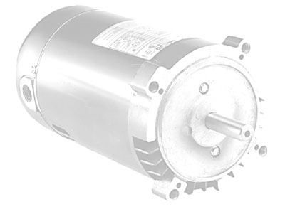
When an electric motor stops running, use your ohmmeter or multimeter to check the electrical system. With an ohmmeter, you can check all grounds; measure the resistance of the motor windings and overload protector; test the capacitor and insulation; and troubleshoot the starting switch.
Some ohmmeters provide a true ohm value reading (typically models with digital readouts/auto scale). Others, such as analog models with needle indicators, feature numerical ranges that reach from R x 1 — in which the meter indicates the actual value in ohms — to R x 100K (100,000 times the indicated value in ohms).
When using a variable-range ohmmeter for testing and troubleshooting, follow the meter maker’s instructions regarding range selection for each test. If your ohmmeter doesn’t have the exact range indicated, use the next higher range. Here, the evaluations are done with analog meters.
Be safety-conscious
Whenever electricity is involved, safety must come first. Prior to conducting any tests, review your safety precautions and disconnect all motor leads from the power source.
Also, perform a visual check of the electrical leads, wires, terminals and contacts, checking for any burned, cut, pinched, frayed or disconnected leads or wires. The following procedures outline test and troubleshooting actions you can take for common servicing.
Ground check
Check: Set the analog ohmmeter to the highest range. Attach one probe to the ground screw and touch the other probe to all electric terminals on the terminal board, switch, capacitor and overload protector.
Troubleshooting: Any ohmmeter reading of less than infinity indicates a ground. If any contact is grounded, check and repair all external electrical leads. If the ground is in the stator, you should replace the motor. Retest the grounds until no readings register on the ohmmeter.
Winding continuity
Check: Set the analog ohmmeter on R x 1. Discharge the capacitor by shorting across the terminals with an insulated screwdriver and compare the following readings with the ohmmeter. Note: Leads can be different, depending on the manufacturer and make.
Assuming the leads function as follows:
L1 = one main winding lead
L2 = second main winding lead
L3 = third main winding lead
L4 = phase, auxiliary or “start” winding lead, then the resistance between L1 and L2 must match the resistance between L2 and L3. And the resistance between L3 and L4 must match the resistance between L1 and L4.
Troubleshooting: If the resistance reading for either of the tests differs, check the external leads for repairs. The indicator may point to “open” for shorted windings, which will require rewinding or replacing the motor.
Capacitor
Check: Set the analog ohmmeter on R x 1K. Discharge the capacitor by shorting across the terminals with an insulated screwdriver. Attach one ohmmeter lead to each capacitor terminal. The ohmmeter needle should move rapidly to the right, then slowly drift to the left. Note: This test only applies to analog meters. If a digital meter is used, readings should start low and rapidly increase to maximum value. You also can use a capacitor meter to see if it is open or shorted.
Troubleshooting: Replace the capacitor if:
The capacitor doesn’t register an ohmmeter value; or, the ohmmeter reading moves to 0 and stays there.
The ohmmeter reading remains at a high value, which indicates an open circuit within the capacitor.
The capacitor’s bleed hole looks stressed or shows signs of corrosion.
Overload protector
Check: Set the analog ohmmeter on R x 1. Check the resistance between the overload protector terminals. Resistance between terminals 1 and 2 (disc) should be approximately 0. Resistance between terminals 2 and 3 also should be approximately 0.
Troubleshooting: Replace the overload protector if either resistance value exceeds 1 ohm.
Starting switch
Check: Set the analog ohmmeter on R x 1. Attach one lead to each switch terminal; the ohmmeter reading should be 0. Flip the rotating switch (governor or actuator) weight into the running position; the ohmmeter reading should be infinity — defined as high resistance/more than 1,000 ohms. Visually check the stationary and rotating switches when the motor is running; switch contacts must be closed when the motor is at rest and open when the motor reaches about two-thirds of full speed.
Troubleshooting: To discount a faulty starter switch, bypass the switch and repeat the above tests. Clean the points with a file or fine sandpaper. Replace the starting switch if it continues to be faulty.


